
Reverse Air Bag House Filter Bag – Storage, Installation, Start-Up And Operation Guide
STORAGE, INSTALLATION, START-UP & OPERATION GUIDE
STORAGE & HANDLING
- The Reverse air filter bags made out of woven glass filter media are very delicate in nature and must be handled with same care as glass.
- Two filter bags are packed in one carton and then four cartons are put in one big carton. Once you receive bags at your works unload them directly at the place of storage and avoid multiple handling as much as possible.
- Bags shall be kept in dry, covered and safe place. If possible cover the stacked filter bags in packed conditions with Tarpaulin to avoid damage due to water spillage or other mechanical means.
- The bags must be kept upright as marked on the cartons. Hooks shall not be used for lifting the cartons as that may damage the bags permanently.
- While moving cartons handle them in upright condition as there are steel parts with the bags, which may damage bags if turned upside down or otherwise. Each carton must be handled individually with due care.
INSTALLATION
- Before installing Filter Bags made out of woven glass fiber filter media, all used filter bags and caps must be removed from the collector. After removing the used filters, thoroughly clean the clean air compartment of the collector.
- Shipping boxes, unopened, should be carried to the collector to prevent the bags from being dropped, dragged or walked on. If the unpacking is to take place on a rough floor, place cardboard or substitute on the floor.
- Bags should be removed individually.
- While holding the cap perpendicular to the bag top, carefully lower the cap below the steel snap band located in the top of the filter bag.
- Adjust the top parallel to the bag and gently pull the bag down onto the cap. The snap band should be fully and evenly seated against the bead of the cap around the entire circumference of the cap. The filter bag must not have any radial clearance with the cap and should fit snuggly.
- Lower a string line from top level platform and attach it to the eye of the bag cap, pull the bag to the upper level and attach eye to the hook portion of the J Hook at the bottom of the support bar. Install such that bag seam faces walkway.
- Pull bag over the thimble at the bottom and secure with a clamp. Bag should be adjusted on the thimble so that no twist is visible in the vertical seam. The cord in the bag must be snug up against the lower edge of the clamp and the clamp must be snug against the bottom edge of the thimble bead. Do not allow the cord in the bag to be squeezed under the clamp.
- Tension the bag at 5-6 lbs/inch bag diameter (i.e., 8” Dia. bag at 40-48 lbs tension.)
- Remove the bag-tensioning tool. Check the spring length after three days of installation and tensioning with gauge and do re-tensioning if required.
START-UP AND OPERATION
REQUIREMENTS FOR A SUCCESSFUL START-UP
- Now that you have completed the installation of the system, you are almost ready to start it up. Operating a bag-house is like flying a plane – the critical moments are at the beginning and end of a run. Improper start-up can lead to long-term negative effects. For example, increased residual pressure drop and partial or total blinding of the bags can result from having too high an initial filtering velocity or early dew-point excursions. Improper shutdown can result in dew point excursions; over or under cleaned bags; inadequate hopper discharge, etc. High temperature applications and those with acid contaminants present in the flue gas are particularly sensitive to start-up and shutdown periods.
- Each application has its special concerns. The bag-house manufacturer should be consulted as to the proper do’s and don’ts for your system, and they should be updated with your local experience.
- Implementation of the following steps will go a long way towards providing a successful initial start-up:
Be certain of the system’s initial state with a thorough inspection.
- Plan ahead. The initial start-up is generally a very hectic time, so be organized by creating a checklist and timetable of what is to happen and when.
- Provide good communication both before and during the start up with operating personnel through a familiarization and training session.
- Define and communicate to all personnel involved, the operating conditions requiring an abort, and the emergency steps required to accomplish it.
- Activate each part of the system carefully and in proper sequence.
- Install and calibrate all monitoring and instrumentation before start-up.
- Pre-coat the bags if required.
- Observe and log all pertinent data at frequent intervals until the system has “settled” out.
- Re-inspect key areas under operating conditions.
- Identify any special required activities of operating personnel for maintaining stable operation.
THE FAMILIARIZATION AND TRAINING SESSION
The operational phase of a fabric filter collection system should start long before the actual start-up. Prior to bringing the collector system on stream, there should be familiarization and training sessions for all O & M personnel. In these sessions, the following subject areas should be covered:
- System design – Define the path of the gas and dust flow through the system.
- Component functions – Describe their purpose and operating position.
- Control system – Produce a system schematic showing the physical location of all control sensors and how they are used to control operation. Identify the interlocking of the control logic.
- Critical limits and alarms – Describe what they mean and what must be done if exceeded.
- Key operating parameters – Specify information and data to be monitored; how and when it must be logged and analyzed. Produce and review a schematic showing the physical location of all monitoring instrument sensors and define their normal operating levels.
- Good operating practices – Under normal conditions.
- Identify and highlight specific NO-NO’s – Those operational steps that could produce permanent damage or create safety problems.
- Preventive maintenance program requirements.
- Start-up and shutdown procedures.
- Emergency shutdown procedures.
- Safety considerations – This training phase is too often treated as “on the job” type training. Such an approach can be both dangerous and costly. It should be the Plant Manager’s and/or the Plant Engineer’s responsibility to see that all responsible O&M personnel are both qualified and trained in the operation and maintenance of the bag-house system prior to start-up.
INITIAL START-UP
1. The initial start-up is potentially the most dangerous time for permanently damaging the fabric. The clean filters have not developed a protective dust cake and are particularly sensitive to dust abrasion; penetration of fine particles causing high, permanent residual pressure drop; blinding or plugging by sticky particulate, and fabric strength reduction from attack by acid gases. Remember, you will have an initial start up from the bag’s perspective, every time you change out a partial or complete bag set. For some applications, the bags should be pre-coated with protective dust prior to the introduction of flue gas. In all cases, the cleaning system should be turned off, and the filtering velocity kept very low until a sufficient dust cake is developed. This is accomplished when a pressure drop of 25-50 mmWG across the bags is reached. A system flow control damper is usually available to regulate and adjust the gas flow. If there is none, the pickup lines should be dampered back by using the balancing blast gates, or by restricting the pick-up hoods with a temporary baffle. The gas flow can then be slowly increased until 100-150 mmWC of pressure drop or the design volume is achieved. [This can take several hours to several days to accomplish depending on your application, but extra attention during this time will significantly extend the life of your bag set and minimize long term pressure drop.] When 100-150 mmWC pressure drop is reached, initiate the cleaning system for one complete cycle. Typically, the pressure drop will fall into the 50-75 mmWC range. Allow the pressure drop to rebuild to the 100-150 mmWC level and again initiate one cleaning cycle. Set the cleaning frequency to approximately the time it takes to rebuild pressure drop to 5”, or if you have a dP initiated cleaning control system, set it to clean at 5” and turn it on. Monitor the rate of pressure drop rise for several days and adjust flange to flange pressure drop in the 6-7” range.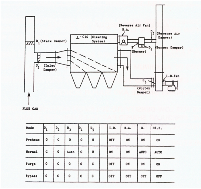
2. System Schematic
Figure 4-1 shows a system schematic for a high-temperature system. Its operational mode chart shows the condition of all critical components for each mode. A schematic and chart of this type should be prominently displayed in the control area. Start-up and shutdown procedures, including emergency shutdown for the system, should also be displayed.
PRECOATING AND INITIAL START-UP GUIDES
Table 4-1 lists acceptable pre-coat materials; Table 4-2 lists pre-coat materials and practices to be avoided. Table 4-3 lists general guidelines for pre-coat and start-up of a full set of bags. Table 4-4 lists general guidelines for the pre-coat and initial start-up of a partial set of bags.
Starting up partial bag sets is actually more difficult in some ways and easier in others. Since the rest of the bag set has a higher resistance to flow, the newly installed bags will try to hog a higher amount of gas flow and this may damage the bags. You must take steps to restrict the flow into the new bags until a protective dust cake has been established. Normally this means, closing the inlet damper on the compartment containing the new bags for a few days, and minimizing the cleaning frequency of that compartment. With non-compartmented pulse jet baghouses, it may require, partially blanking off the new bags if start up at high flows is deemed destructive to new fabric.
One way that starting up partial bag sets is easier is that the process can be stabilized while filtering through the older compartments, and thus potentially damaging gas and particulate can be avoided during the initial operation of the new bags.
ACCEPTABLE PRECOAT MATERIALS
|
PRECOATING AND INITIAL START-UP OF A TOTAL SET OF BAGS1. TURN OFF THE CLEANING SYSTEM AND PLACE ALL COMPARTMENTS ON-LINE. 2. WITH THE PROCESS OFF LINE, BRING THE AIR FLOW THROUGH THE BAGHOUSE TO AS CLOSE TO DESIGN FLOW AS POSSIBLE. 3. INJECT 0.05-0.1 POUNDS OF PRECOAT MATERIAL PER SQUARE FOOT OF FABRIC AREA TO BE COATED IN A MANNER THAT MAXIMIZES THE UNIFORM ENTRAINMENT OF THE MATERIAL INTO THE GAS STREAM AND DELIVERY TO ALL FABRIC AREAS. 4. STOP THE AIRFLOW THROUGH THE BAGHOUSE AND PERFORM A VISUAL INSPECTION OF THE CLEAN AIR PLENUM, (WITH OR WITHOUT THE AID OF FLUORESCENT POWDER AND A LEAK DETECTOR LIGHT SOURCE), AFTER PRECOATING AND PRIOR TO THE INTRODUCTION OF FLUE GASES. 5. IF POSSIBLE, START THE PROCESS WITH THE BAGHOUSE ON BYPASS UNTIL STABLE OPERATION HAS BEEN ACHIEVED AND THE FLUE GAS TEMPERATURE HAS EXCEEDED THE EXPECTED DEW POINT TEMPERATURE WITH SOME SAFETY MARGIN. 6. INTRODUCE FLUE GAS TO THE BAGHOUSE AT 50-60% FLOW RATES AND MONITOR FLANGE-TO-FLANGE PRESSURE DROP AND OUTLET TEMPERATURE. IF THE TEMPERATURE CAN NOT BE MAINTAINED ABOVE THE ACID DEW POINT, SOME COMPARTMENTS SHOULD BE REMOVED FROM SERVICES. 7. WHEN THE FLANGE-TO-FLANGE PRESSURE DROP REACHES 4-6 INCHES, INITIATE ONE COMPLETE CLEANING CYCLE. THE PRESSURE DROP SHOULD BE REDUCED TO THE 1-2 INCH LEVEL FOLLOWING CLEANING AND TAKE SEVERAL HOURS TO RISE AGAIN TO THE 4-6 INCH LEVEL. IF THIS OCCURS, SET THE CLEANING CONTROLS TO AUTOMATICALLY CLEAN AT 6 INCHES AND MONITOR THE PRESSURE DROP CHARACTERISTIC UNTIL STABLE OPERATION IS ACHIEVED. 8. FOLLOWING 1-2 CYCLES, INCREASE FLOW RATES TO FULL DESIGN |
PRECOAT AND INITIAL START-UP OF PARTIAL SET OF BAGS1. TURN OFF THE CLEANING SYSTEM IN THE COMPARTMENTS BEING PRECOATED. 2. INJECT 0.05-0.1 POUNDS (DEPENDING ON VENDORS RECOMMENDATION) OF PRECOAT MATERIAL PER SQUARE FOOT OF FABRIC AREA TO BE COATED, SIMULTANEOUSLY WITH THE INITIAL INTRODUCTION OF FLUE GAS INTO THE NEWLY REBAGGED COMPARTMENTS. THIS IS NORMALLY DONE THROUGH THE HOPPER TO DIRECT THE PRECOAT MATERIAL TO THE NEW FABRIC. 3. FOLLOWING COMPLETION OF PRECOAT INJECTION INTO A COMPARTMENT, REDUCE THE GAS FLOW THROUGH THE COMPARTMENT BY CLOSING THE INLET OR OUTLET DAMPER AT LEAST 50%. THIS IS TO LOWER THE FILTERING VELOCITY TO BELOW DESIGN LEVEL AND PROTECT THE FABRIC FROM DEEP PARTICLE PENETRATION WHICH WILL CREATE A PERMANENT INCREASE IN THE RESIDUAL PRESSURE DROP. IF LEFT FULL OPEN, THE NEWLY BAGGED COMPARTMENTS WILL OPERATE AT HIGH FILTERING VELOCITIES DUE TO THEIR INITIAL LOWER RESISTANCE TO FLOW. 4. MONITOR THE NEWLY BAGGED COMPARTMENT’S TUBE SHEET PRESSURE DROP AND INITIATE ONE CLEANING CYCLE WHEN IT REACHES THE 4-6 INCH RANGE. IF INDIVIDUAL COMPARTMENT OR BAG FLOW INSTRUMENTATION IS AVAILABLE, ADJUST THE INLET DAMPER TO RESTRICT PEAK FILTERING VELOCITY TO BELOW DESIGN LEVEL. REPEAT 2-3 TIMES. 5. PLACE THE NEWLY BAGGED COMPARTMENT BACK INTO THE AUTOMATIC CLEANING CYCLE, AND LEAVE THE DAMPER PARTIALLY CLOSED FOR ANOTHER 49 HOURS. 6. OPEN THE DAMPERS TO THEIR FULL POSITION AND CONTINUE NORMAL OPERATION. |